


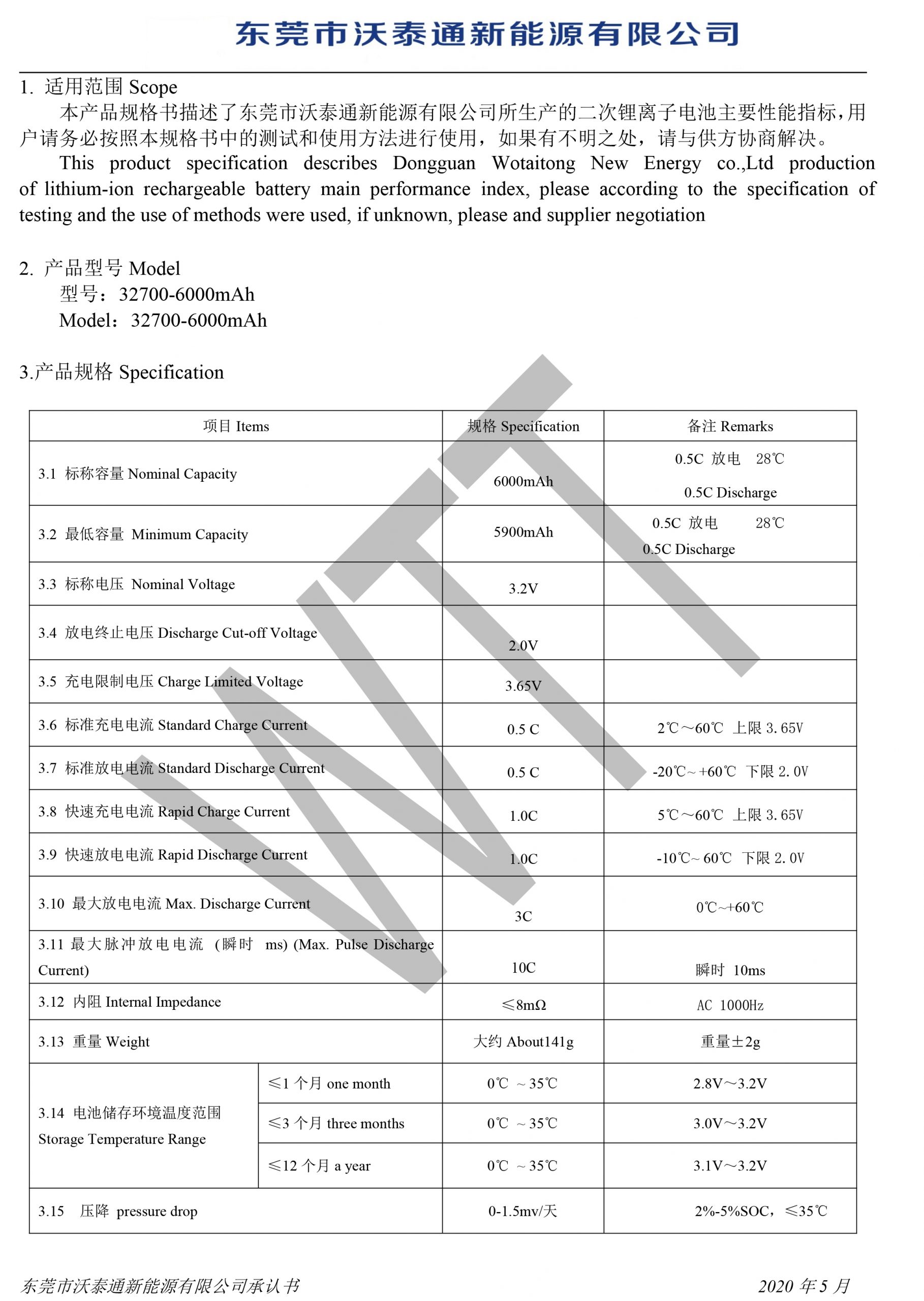
| Specifications: | – |
|---|---|
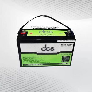
| Nominal Voltage | 12.8V |
| Nominal Capacity (1Hr) | 110Ah |
| Case Dimensions (L x W x H) | 328mm x 171mm x 215mm |
| Weight | 13.3 Kgs |
| Cycling voltage | 11.5 ~ 14.6V |
| Charge voltage | 14.0 ~ 14.6V |
| Float Voltage | 13.5 ~ 13.7V |
| Maximum Charge Current | 100A |
| Recommended Charge Current | ≤70A |
| Maximum Discharge Current | ≤200A for 5mins150A Continuous |
| DCS BMS (internal) | DCS active cell management system, over/under voltage, over current charge/discharge, low/high temperature protections |
| Cell Chemistry | DCS 3.2V 5.0 – 7.2Ah Cylindrical (LifePO4) |
| Cycle Performance | 2500 Cycles @ 100% DOD |
| LCA | 1000 |
| Ingress Protection | IP54 |
| Case | ABS (flame retardant plastic) |
| Operating temp Range | -30 to +110 degrees C |
| Terminals | Top Mount M8 Stainless steel / Copper |
| Parallel Connections Only | YES |
| Series Connections | No |
| Warranty | 4 years | 3 years under bonnet |
DOWNLOAD APP (DCS LFP)
DCS Bluetooth Technology powered by DCS LFP, this APP is only for DCS LFP batteries which is based on BLE 4.0 technology. Every DCS battery pack comes standard with our detailed battery monitoring via Bluetooth.
This App provides comprehensive monitoring for DCS LFP batteries, including:
- SOC%
- Time Remaining
- Battery pack voltage, Power & Current
- Battery Management MOSFET temperature
- Individual Cell Status with balancing indicators.
- Connectivity distance up to 10 meters.
- Every DCS battery pack comes standard with our detailed battery monitoring via Bluetooth
![]()
All DCS batteries now feature our comprehensive Bluetooth System available on both Android and Apple operating systems shows a lot of cool things.
- Cell status showing real time cell balancing operation
- BMS MOSFET temperature ( great info when your winching or running a large inverting load or your trolling motor to know how hard your pushing the electronics ).
- SOC% estimate (using impedance tracking – the App learns the SOC after the first 10 cycles)
- Battery pack voltage and cycle count
- Amp meter – showing charge and discharge current
- Connectivity distance up to 10m
- Now there is no need to install battery monitors or shunts in boats, campers or vehicles. You have all the info you need at your finger tip.
- The SOC estimate is accurate on single batteries, the more batteries that are expanded in parallel the less accurate the SOC becomes.
- This free application provides the perfect tell-tale about the battery packs state of health as it ages
- Assists installers & integrators to quickly diagnose any system issues
DCS 6AWG 230MM PARALLEL CABLES WITH M8 RING TERMINALS

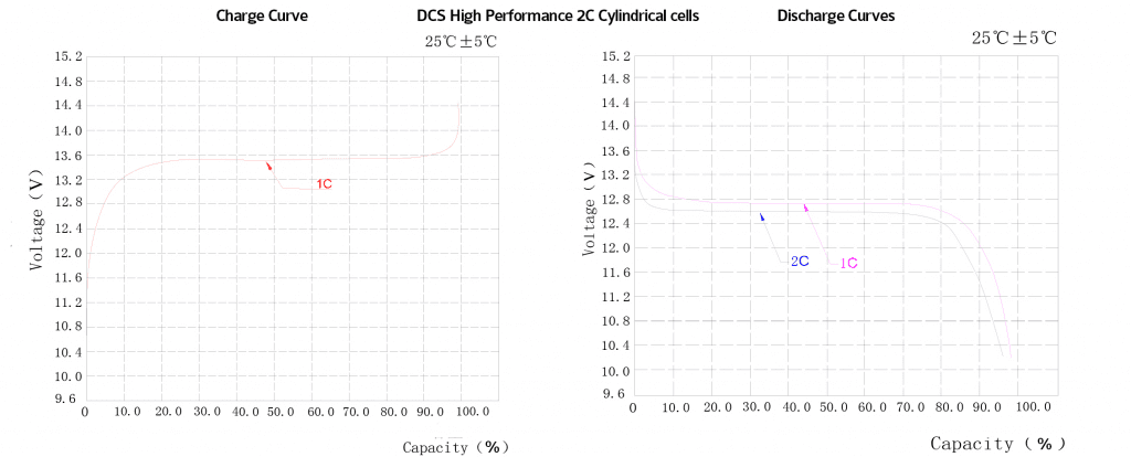
DCS HIGH PERFORMANCE 2C CHARGE & DISCHARGE CURVES
CELL SAFETY INFO - WHY LIFEPO4 (LFP)?
Lithium Ferrophosphate (LFP) is a flame retardant, stable, safe and proven cell chemistry that has a very good energy density around 325 Wh/L. This cell chemistry can be engineered for various applications by adjusting the ratio of elements to provide high performance characteristics. E.g. the DCS marine battery range runs 2C cells, which means our little 75Ah battery will discharge comfortably at 75Ah x 2C = 150A. The DCS 80Ah Extreme runs 10C cells which means the 80A can comfortably discharge at 80Ah x 10C = 800A but is of course limited to lower currents due the the Battery Management System. LFP also has very good cycling durability between 2,000 ~ 12,000 cycles can be achieved depending on how well the cells are managed, and the lowest rate of capacity loss (aka greater calendar-life) compared to other lithium cell chemistries.
WHY YOU CANNOT USE A VSR BETWEEN TWO DIFFERENT BATTERIES CAPACITIES & CHEMISTRIES?
Battery cells are simply a bunch of resistors with the ability to store energy. A 100Ah battery pack has a different resistance characteristic compared to a 50Ah battery pack, that theoretical difference in resistance is 2:1. So if you connect a 100Ah battery in parallel to a 50Ah battery there is no way for these two batteries to equalise and therefore you can’t charge them correctly. So for example connecting a 60Ah calcium starting battery to a 120Ah AGM via a VSR (Voltage Sensing Relay) you cannot charge both batteries correctly and from that day onwards you are prematurely destroying both battery packs. Same theory applies with lithium’s it’s still a battery pack. What’s the solution? A DC-DC charger, you now have a permanent point of isolation (meaning that both batteries are never connected to each other in parallel). The DC-DC charger takes the surplus power from battery A (engine) and chargers battery B (aux/house). This device now allows any battery capacity and or chemistry to be used.
WHAT IF BOTH BATTERIES ARE THE SAME, CAN I RUN A VSR BETWEEN EXACTLY THE SAME TWO BATTERIES?
Yes you can, but lithium’s have a different voltage curve, so you would still need to use a programmable VSR to dial them in correctly. You would also need to ensure the batteries are programmed to never exceed a 10%SOC variance, any larger and you risk damaging the BMS’s. These devices also draw a lot of power when engaged to so it’s best to run the two batteries in permanent parallel and run a load disconnect instead of a VSR.
THE ADVANTAGES OF THE LITHIUM BATTERY CELL CHEMISTRY
Lithium battery cells have a super low resistance so are very easy to charge and very efficient. This level of efficiency means you can charge them at very high C rates. For example if you look at the charge rate of a 100Ah AGM battery the recommended charging current will be around 25A, which is a 0.25C charge rate. If you consider the DCS 12V 100Ah Lithium battery it can be charged at up to 70A which is a 0.70C charge rate. This means you no longer need to consider DC-DC chargers as you can connect our batteries directly to high power charging devices such as suitable alternators, or large buck boosters. For example our popular dual 90Ah battery system for boats and 4WD vehicles, can be connected to alternators up to 160A.
WHY CAN DCS BATTERIES BE CONNECTED IN PARALLEL WITHOUT ANY EXTERNAL COMMUNICATION SYSTEM?
Because our batteries are internally voltage regulated and because our BMS has such a high sustainable peak discharge current they will do an amazing job of equalising very quickly.
WHAT HAPPENS IF I FULLY DISCHARGE MY BATTERY TO EMPTY?
The BMS will emergency open circuit the battery terminals to protect the cells. This means there is no longer any resistance in the system. The BMS needs a 12V supply with at least 1A of current to release and wakeup from a cell emergency protection state. Most mains chargers with a lithium profile will do a slow recovery charge as will most solar regulators. Some chargers on the market today that are advertised as ‘lithium’ compatible still don’t have the firmware to do a slow recovery charge to release BMS’s. If you have a charger that will not wakeup the BMS, easiest way to wake it up is to connect a unregulated solar panel directly to the battery terminals, ensure all loads are disconnected before you do this. Having said that every system should have a suitable low cut off voltage to shutdown loads/accessories so that the batteries are not fully drained. “Batteries cannot be left flat/empty, if the low voltage cutoff is triggered the battery pack should be fully charged as soon as possible. If access to a suitable charger is not possible, disconnect all loads from the battery terminals. The warranty will be void if the battery pack has been left in a low voltage cutoff state for longer than 14 days.” Most important thing is to isolate everything from the battery terminals, as cables/loads connected to the terminals causes more power drain as the FET gates have to remain closed to cull the accessory standby loads connected to the battery pack + offset BMS standby power consumption.
BATTERY MONITOR SETTINGS
Use the following settings: Charged voltage 14.0V Tail current 4% Charged detection time 1min Peukert 1.05 Charge efficiency 98% Current threshold 0.1A C rates: refer to the battery pack capacity
WHAT IS THE BEST STATE/CHARGE TO STORE THESE BATTERIES ?
Fully charge to 100% isolate everything from the terminals and leave for max 3 months and then cycle (fully discharge and fully charge) and leave again for 3 months etc…. Minimum 4 cycles per year to not effect the cells capacity.
WHAT SOC DO MODERN SMART ALTERNATORS TYPICALLY CHARGE BATTERIES TO?
The reason many factory batteries fall over after 9/12 months is because modern/smart alternators typically drop the alternators voltage output to 13.5/13.6V. This voltage is not high enough to charge wet/calcium/lead acid batteries so from the getgo they are destined to fail prematurely. They are typically under charged to around ~80%SOC at these voltages. So what happens when DCS Hybrid batteries are connected to smart alternators? Exactly the same thing they get charged to around the same 80%SOC. However because LFP has no memory effect that’s perfectly fine. By only charging to 80% you are further improving the service life of our batteries. It’s no not necessary to charge our batteries over 80%SOC. The only advantage is that you give the BMS a chance to detect full charge voltage and calibrate the SOC readout. So try to plug into mains once a week to fully charge your batteries, especially if your not running any fixed solar supply.
WHAT ARE OUR 2C CELL SPECIFICATIONS?
RECOMMENDED CHARGER SETTINGS FOR DCS 12V BATTERIES:
Bulk: 14.4V Float: 13.5V
SOC% OUT - HOW TO RESET?
When the battery pack is discharged down to 11.50V the BMS resets to 0%SOC and now is placed in a relearning state – the pack must be fully charged continuously without stopping to calibrate again. Charge it on a mains charger to 14.60V. Depending on the usage pattern, best to fully cycle the batteries once every 3 months to give the cells a refresh. To fully cycle a 12V pack discharge to 11.50V and charge to 14.60V.
- 200A continuous operations using high-quality components
- To have a minimal increase in temperature at peak output current (as these circuit boards are installed inside battery packs, limiting internal heat build-up that is crucial for the longevity of the battery cells).
- Designed for engine cranking applications, it has to deliver a minimum of 1200LCA’s for 10 seconds (because of the limited voltage drop with suitable lithium cells, it’s very easy to crank over modern engines. Most engines will start in under 1sec, so 10 seconds is plenty). CCA’s don’t apply to lithium batteries as this standard was developed for lead-acid batteries and needed to deliver 30 secs of cranking amps. When a lithium battery is controlled via a BMS, the correct terminology is LCA = Lithium Cranking Amps based on delivering 10 secs of cranking amps.
- Suitable for high temperatures applications, e.g. engine compartments. It will be stable up to 180 degrees C.
- Bluetooth and WiFi connectivity in order to develop a comprehensive app platform
- Pass MIL vibration testing standards (to open up the development of batteries for just about any application).
In a nutshell, the design needed to be tough and reliable for those who use them in the field with no room for error. The construction materials, coating and surfaces, assembly techniques are critical in designing a reliable system. After submitting our brief to all major leading manufacturers in Europe, Japan, USA and Korea, we assessed their expertise and ended up working with a leading and well known Japanese semiconductor manufacturer.
This is a typical Chinese 100A 4S BMS design
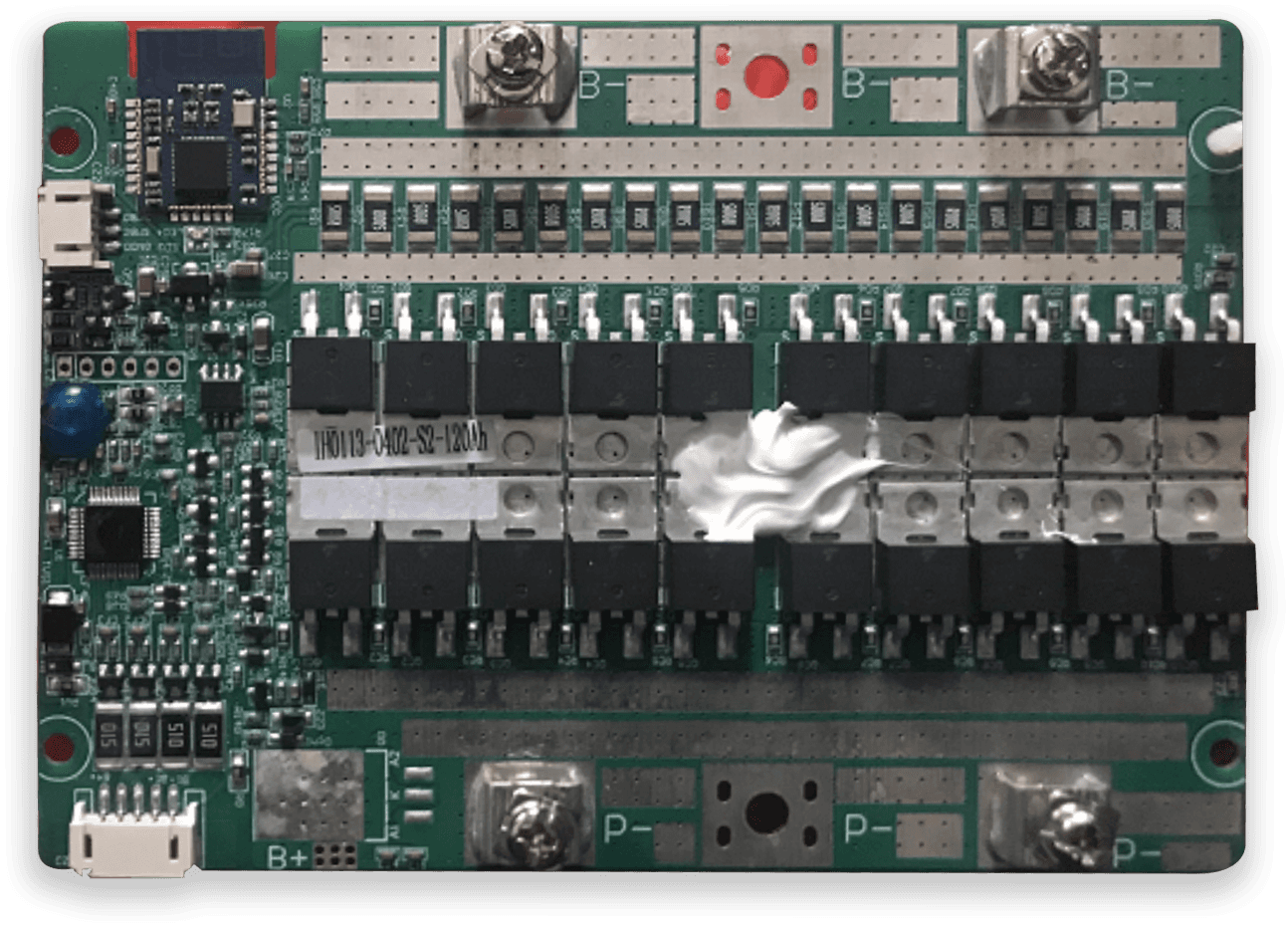
This is the DCS 4S 200A BMS
DCS CELL MANAGEMENT SYSTEM:
Having developed such an industry-leading and reliable BMS, it made no sense to combine the cell balancing system together with the BMS. So with our many years of experience in designing and maintaining lithium batteries, we have developed a stand-alone CMS to compliment our BMS. CMS? What? OK, so there are two ‘theories’ of cell balancing in the lithium world passive and active. Passive balancing is a cheap inferior method of cell management as it can burn resistors in an attempt to bleed cell strings. In contrast, active cell balancing is a more complex and efficient balancing technique that redistributes charge between battery cells during the charge and discharge cycles.
Passive balancing has two fundamental setbacks;
- Heat: We don’t want unnecessary heat build-up inside a battery pack. The less internal heat, the lesser the impact on the battery cells over time
- Resistors have a limited service life, and once they fail game over, you have no cell management. But more importantly, they can fail in such a way in which they will keep drawing power and eventually destroy the cells.
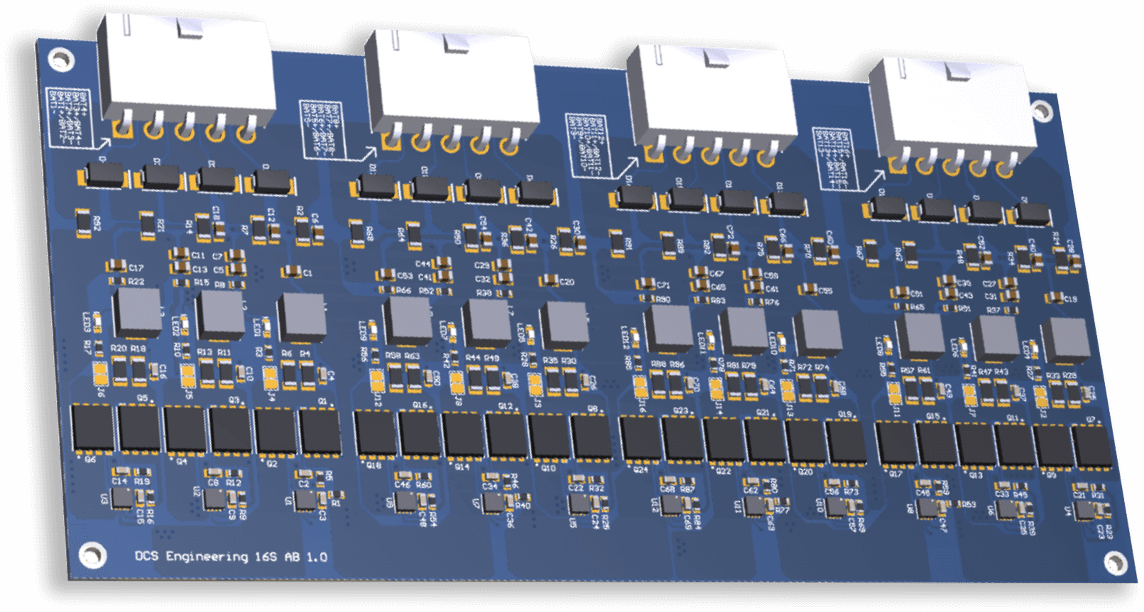
- High current movement (our latest boards now achieve 3.7A dynamic movement per channel)
- Thermal management to ensure the boards remain reliable in harsh environments
- Be able to withstand maximum current and thermal loads to ensure long term reliability
- Fail-safe design, if any component fails, it won’t compromise the battery pack (not consume power from the battery cells)
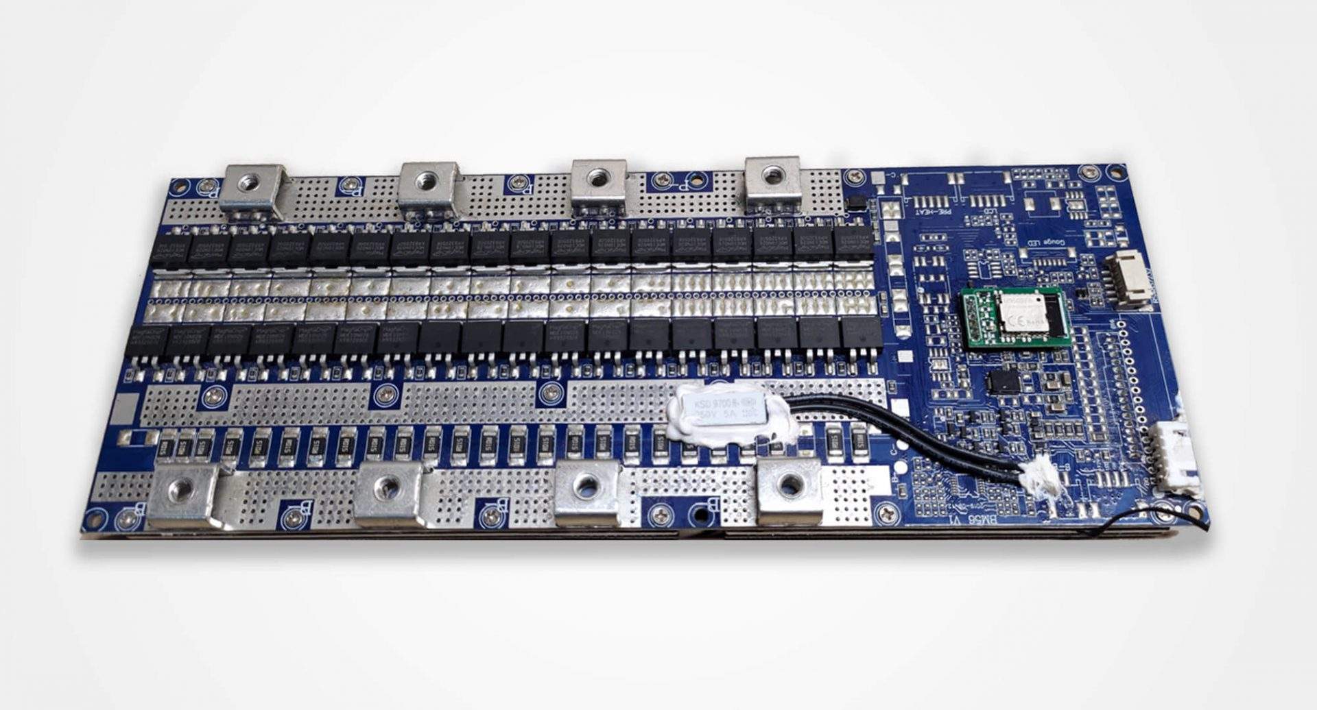
This is the DCS 16 channel CMS
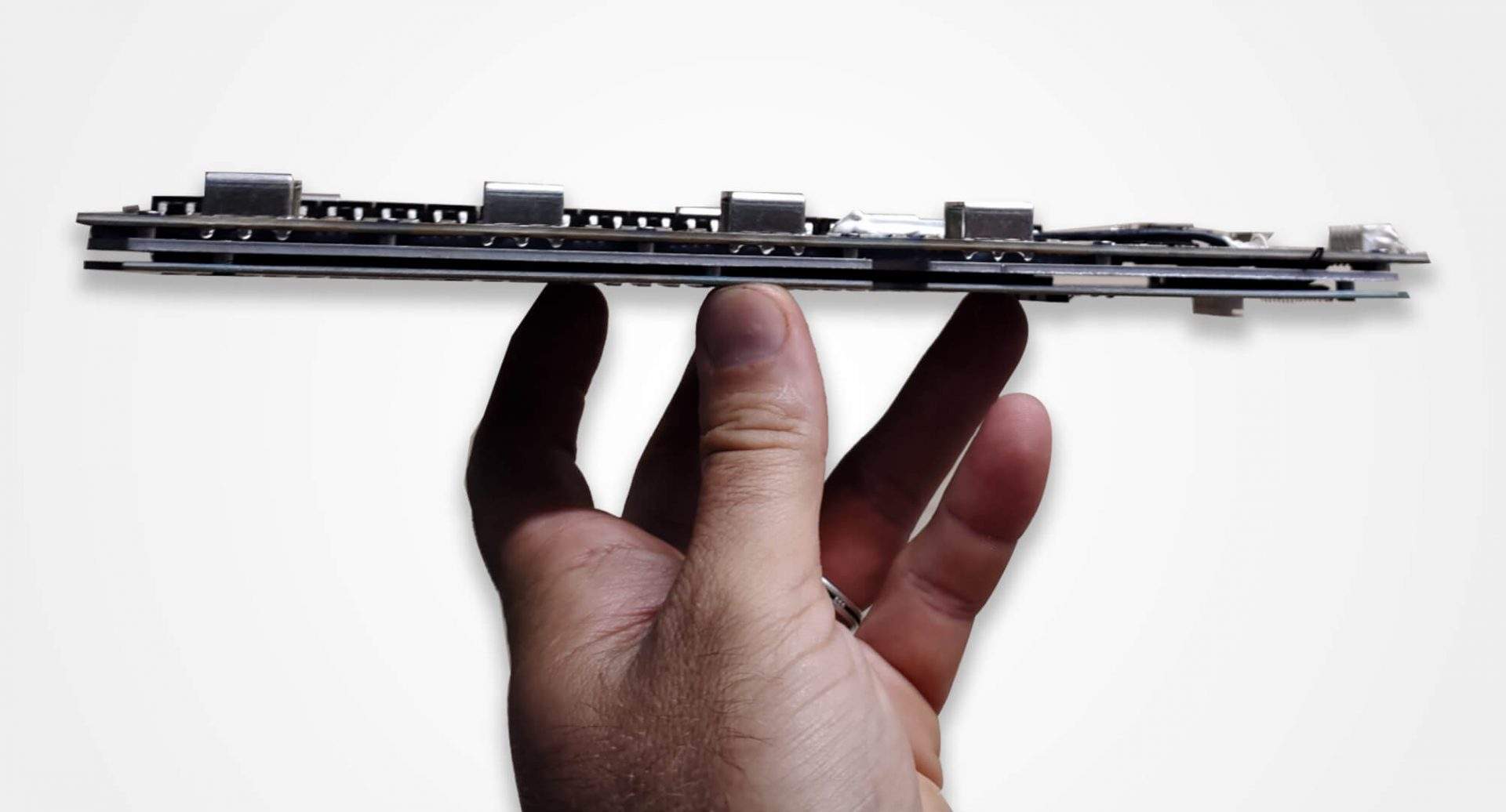
We design all our own PCB hardware and the circuit boards are tested to withstand a minimum of 10 years of severe abuse. This video is the MIL-STD 810G Method 514.6 which includes 4 procedures for different modes of vibration.
How to configure the DCS 12V 110Ah Marine batteries and the DCS 12V 80Ah Extreme batteries into any vessel.


Reviews
There are no reviews yet.